
PCI 配置空间介绍
经常和虚拟化打交道, 一定会涉及到虚拟设备的初始化, 这就需要对硬件的初始化操作有一定的了解. 初始化硬件设备, 主要就是激活IO port 和IO memory的功能, 对于一些PCIe设备, 还可能需要激活一些capabilities. 本文的内容不是有条理的介绍, 更偏向于资料的整理. 希望可以帮助到大家.
PCI
PCI配置空间和内存空间是分离的,那么如何访问这段空间呢?我们首先要对所有的PCI设备进行编码以避免冲突,通常我们是以三段编码来区分PCI设备,即Bus Number, Device Number和Function Number,以后我们简称他们为BDF(已知大部分VID表 )。为了保证其唯一性,Vendor ID应当向PCI特别兴趣小组(PCI SIG)申请而得到。
为了为PCI设备分配CPU-relative space,计算机系统需要知道其所申请的地址空间的类型、基址等,这些信息记录在设备的BAR中,每个PCI配置空间拥有6个BAR,因此每个PCI设备最多能映射6段地址空间(实际很多设备用不了这么多)。PCI配置空间的初始值是由厂商预设在设备中的,于是设备需要哪些地址空间都是其自己定的,可能造成不同的PCI设备所映射的地址空间冲突,因此在PCI设备枚举(也叫总线枚举,由BIOS或者OS在启动时完成)的过程中,会重新为其分配地址空间,然后写入PCI配置空间中。
通过memory space访问设备I/O的方式称为memory mapped I/O,即MMIO,这种情况下,CPU直接使用普通访存指令即可访问设备I/O。
通过I/O space访问设备I/O的方式称为port I/O,或者port mapped I/O,这种情况下CPU需要使用专门的I/O指令如IN/OUT访问I/O端口。
常见的MMIO例子有,VGA card将framebuffer映射到memory space,NIC将自己的片上缓冲映射到memory space,实际上,最典型的MMIO应该是DRAM,它将自己的存储空间映射到memory space,是占用CPU地址空间最多的“设备”。
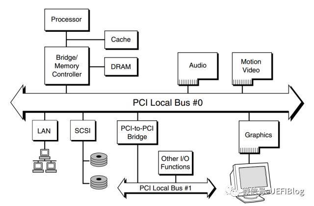
一个典型的PCI架构如下:
PCIe
PCI是并行总线, 虽然表面上看, 并行总线会比串行总线一次性串数的数据更多, 但是随着频率的提高, 线路干扰越加严重, 而且并行传输对线路的一致性要求非常高, 设计更加麻烦, 而串行总线通过提高频率, 可以有效提高传输速度和传输质量, 因此PCIe采用了串行差分信号传输.
Intel pci 寄存器格式
有了BDF我们既可以唯一确定某一PCI设备。不同的芯片厂商访问配置空间的方法略有不同,我们以Intel的芯片组为例,其使用IO空间的CF8h/CFCh地址来访问PCI设备的配置寄存器 (参考Accessing PCI Express* Configuration Registers Using Intel® Chipsets).
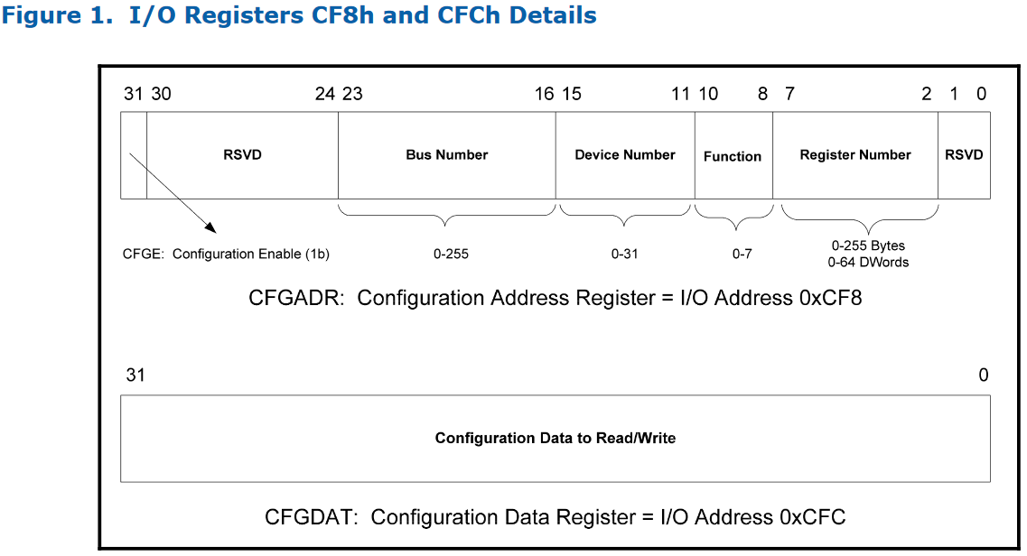
当我们需要获取/修改特定设备值时:
1 | write((1<<31)|(bus number<<16)|(dev number<<11)|(func number<<8)|reg_number, 0xcf8)**; |
关于如何配置PCI空间, 可以参考此链接.
PCI配置空间
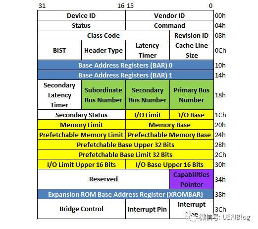
PCI设备都有一个256字节的配置空间, 前0x40 bytes有固定的格式规范, header type 为 0 的结构如下:
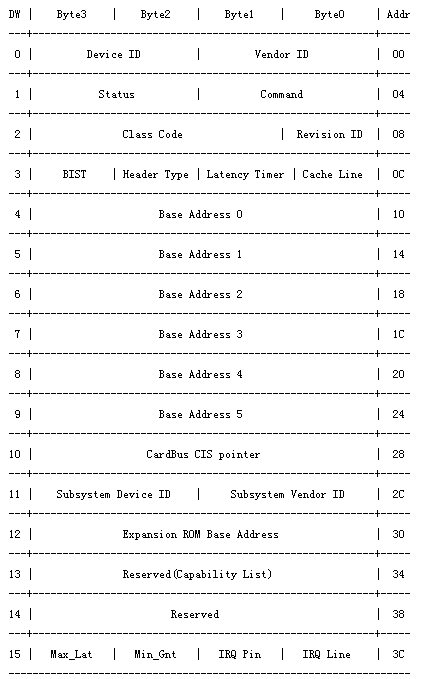
其中Device ID和Vendor ID是区分不同设备的关键,OS和UEFI在很多时候就是通过匹配他们来找到不同的设备驱动(Class Code有时也起一定作用)。更多参考 或者 PCI Local Bus Specification 第六章.
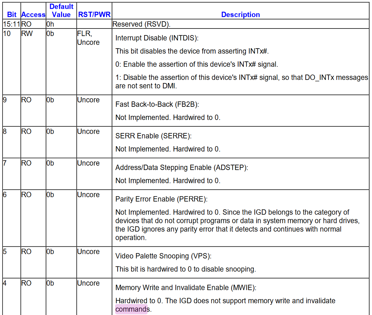
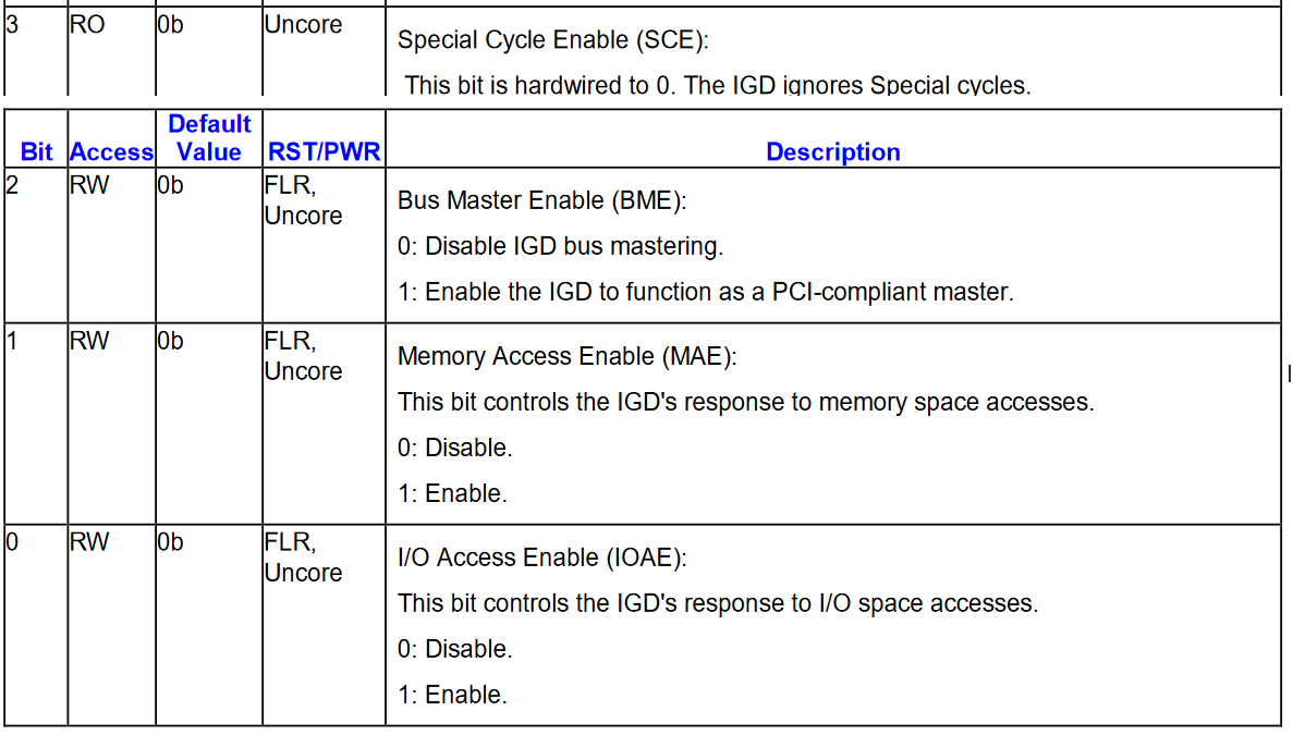
command 细节说明:
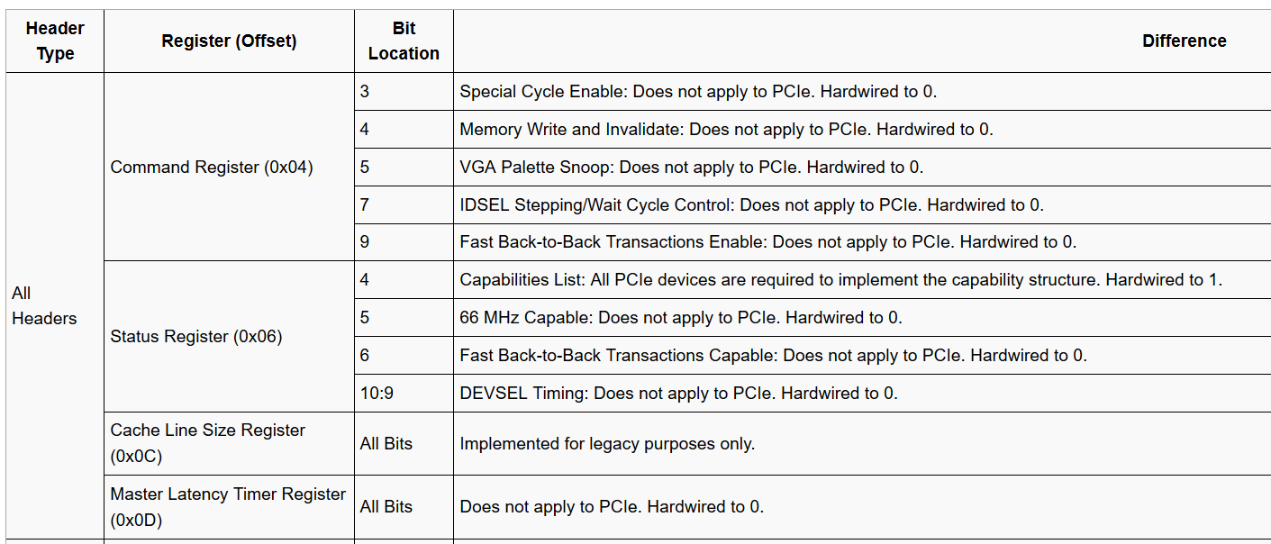
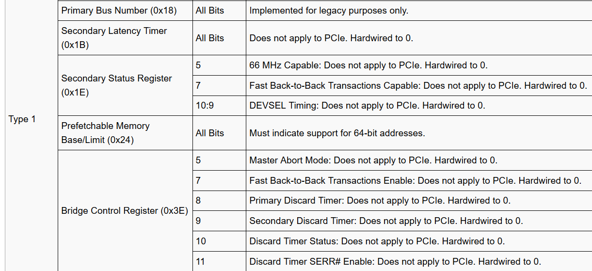
与PCIE配置差异
| Type 0 | Base Address Registers (0x10:0x24) | All Bits | PCIe Endpoint devices must set the BAR’s prefetchable bit while the range does not contain memory with read side-effects or where the memory does not tolerate write merging. 64-Bit Addressing MUST be supported by non legacy Endpoint devices. The minimum memory address range requested by a BAR 128-bytes. |
|---|---|---|---|
| Type 0 | Min_Gnt/Max_Lat Registers (0x3E:0x3F) | All Bits | Does not apply to PCIe. Hardwired to 0. |
Enhanced Configuration Mechanism
PCIe配置空间
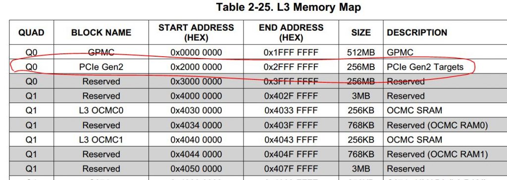
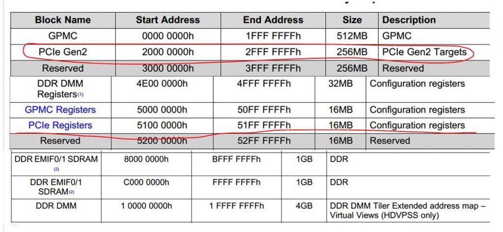
PCIe规范为每个PCIe设备添加了更多的配置寄存器,空间为4K,尽管CFG_ADDR和CFG_DATA寄存器方法仍然能够访问lower 255 bytes,但是必须提供另外一种方法来访问剩下的(255B~4K)range寄存器。Intel的解决方案是使用了预留256MB内存地址空间,对这段内存的任何访问都会发起PCIe配置cycle。
由于4K的配置空间是directly mapped to memory的,那么PCIe规范必须保证所有的PCIe设备的配置空间占用不同的内存地址,按照PCIe规范,支持最多256个bus,每个Bus支持最多32个PCIe devices,每个device支持最多8个function,也就是说:占用内存的最大值为:256 * 32 * 8 * 4K = 256MB。被PCIe配置空间占用的256M内存空间会屏蔽掉DRAM使用该段内存区,这些地址都由CPU出厂时已经固化好了。老男孩读PCIe之六:配置和地址空间, 从cpu角度理解pcie.
下图是ARM Cortex-A9 datasheet内存地址分配局部图:
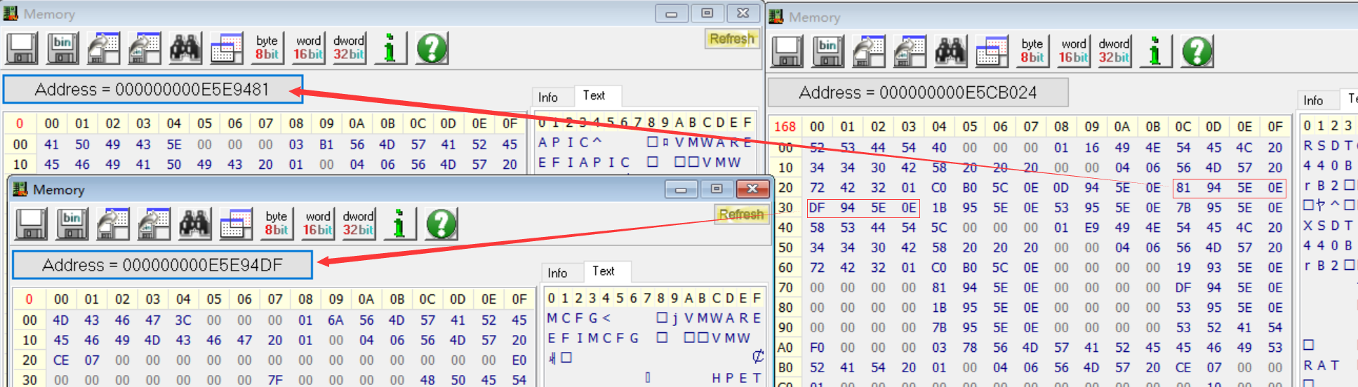
下图是Ubuntu Guest的cat /proc/iomem的截图:

图中的MMConfig(也叫 MMCFG) 就是PCIe的配置空间的映射地址. 因为只有0x80个bus, 所以size为 0x1000 * 8 * 32 * 128 = 0x800,000.
0000:00:0f.0 的意义是:segment number: bus number : device number: function number
下图是windows的RWeverything工具读取的内容:
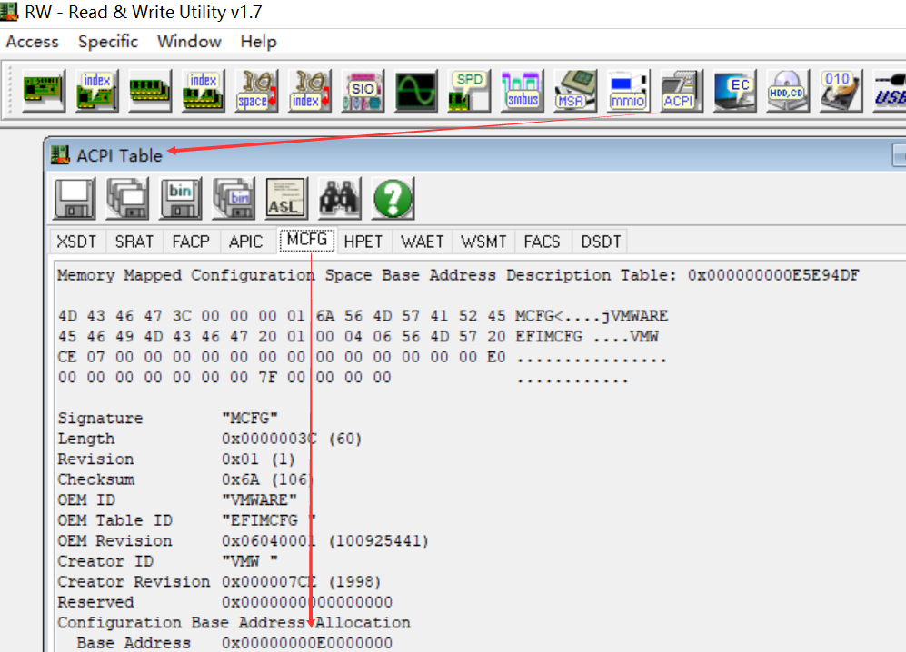
关于如何获取该地址, 参见后续ACPI章节.
windows 获取ACPI的MCFG也可以通过FirmwareTablesView 工具读取MCFG表, 获取0x2C位置的地址, 即为segment0对应的baseAddr.
访问PCIe设备配置空间时候需要手动计算访问PCIe配置空间的地址。计算发放如下:
SIZE_PER_FUNC = 4K = 1000h (fn<<12)
SIZE_PER_DEVICE = 4K * 8 = 8000h (dev<<15)
SIZE_PER_BUS = 4K * 8 * 32 = 100000h (bus<<20)
访问总线号为busNo,设备号为DevNo,功能号为funcNo的offset寄存器的计算公式是:
Memory Address = BaseAddr+ busNo * SIZE_PER_BUS+ devNo * SIZE_PER_DEVICE+ funcNo * SIZE_PER_FUNC+ offset
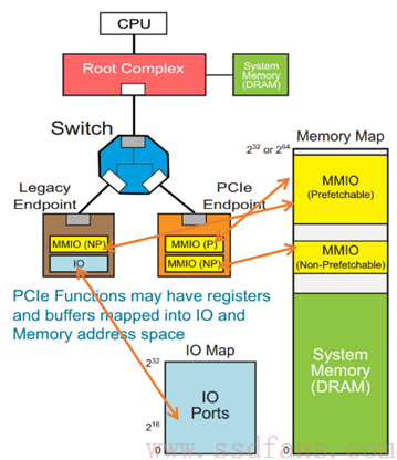
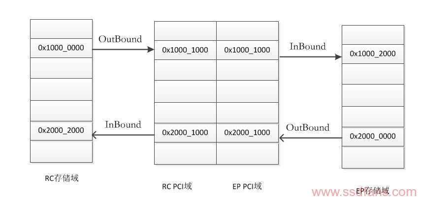
PCIe在存储域地址空间分为三部分,PCIe控制器本身的寄存器、PCIe设备的配置空间、PCIe设备空间。寄存器和配置空间由处理器本身决定存储地址范围,ARM Cortex-A9 处理器地址范围如下图所示,配置空间地址、寄存器地址及内存地址都已经确定。PCIe设备空间需要编程人员去配置Outbound和Inbound寄存器组,确定映射关系。
Outbound在PCIe控制器中扮演的角色是将存储地址翻译到PCIe域的PCIe地址,Inbound是将PCIe地址翻译成存储地址,下图是一个完整的RC和EP模型地址翻译模型,图中的地址数字仅仅代表一种形态,具体地址应该是什么在后文中讲解。当cpu需要访问EP的内存空间时,首先应该将存储地址转换成PCIe地址,在根据TLP到达指定的EP,进而将PCIe地址转换成EP端的存储地址。参考
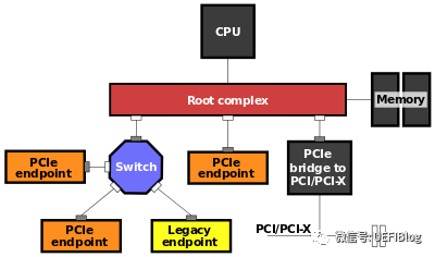
RC(Root Complex)
CPU只能直接访问Host内存(Memory)空间(或者IO空间,我们不考虑),不对PCIe等外设直接操作。RC可以为CPU分忧。
CPU如果想访问某个设备的空间,由于它不能(或者不屑)亲自跟那些PCIe外设打交道,因此叫太监RC去办。比如,如果CPU想读PCIe外设的数据,先叫RC通过TLP把数据从PCIe外设读到Host内存,然后CPU从Host内存读数据;如果CPU要往外设写数据,则先把数据在内存中准备好,然后叫RC通过TLP写入到PCIe设备。 以下是图形示例:
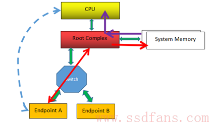
上图例子中,最左边虚线的表示CPU要读Endpoint A的数据,RC则通过TLP(经历Switch)数据交互获得数据,并把它写入到系统内存中,然后CPU从内存中读取数据(紫色箭头所示),从而CPU间接完成对PCIe设备数据的读取。
具体实现就是上电的时候,系统把PCIe设备开放的空间(系统软件可见)映射到内存空间,CPU要访问该PCIe设备空间,只需访问对应的内存空间。RC检查该内存地址,如果发现该内存空间地址是某个PCIe设备空间的映射,就会触发其产生TLP,去访问对应的PCIe设备,读取或者写入PCIe设备。
BAR(base address register)
Bar内存空间的细节:

计算bar空间大小方式如下:
- 向bar 写入全1
- 读回寄存器里面的值,然后clear 上图中特殊编码的值,(IO 中bit0,bit1, memory中bit0-3)
- 取反+1, 得到空间大小.
映射地址空间
使用I/O内存首先要申请,然后才能映射,使用I/O端口首先要申请,对I/O端口的请求是让内核知道你要访问该端口,内核并让你独占该端口. 申请I/O端口的函数是request_region, 申请I/O内存的函数是request_mem_region。request_mem_region函数并没有做实际性的映射工作,只是告诉内核要使用一块内存地址,声明占有,也方便内核管理这些资源。重要的还是ioremap函数,ioremap主要是检查传入地址的合法性,建立页表(包括访问权限),完成物理地址到虚拟地址的转换。
可以通过cat /proc/ioports 和cat /proc/iomem 来查看系统已有的映射情况.
workstation更换memory 地址
- write 新地址到bar
- 重新激活command的第2个比特. 这样映射就会生效
PCI to PCI bridge
它的配置空间如下:
其中的三组绿色的BUS Number和多组黄色的BASE/Limit对,它决定了桥和桥下面的PCI设备子树相应/被分配的Bus和各种资源大小和位置。这些值都是由PCI枚举程序来设置的。
Capabilities
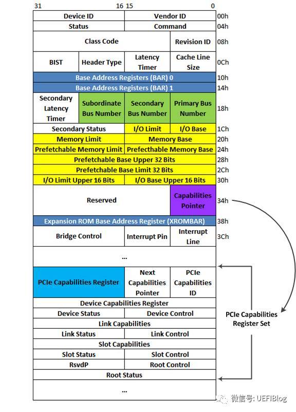
PCI-X和PCIe总线规范要求其设备必须支持Capabilities结构。在PCI总线的基本配置空间中,包含一个Capabilities Pointer寄存器,该寄存器存放Capabilities结构链表的头指针。在一个PCIe设备中,可能含有多个Capability结构,这些寄存器组成一个链表,其结构如图:
示例
HDAudio的配置空间说明如下:
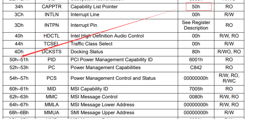
以下是Workstation模拟的HDAudio的配置空间:
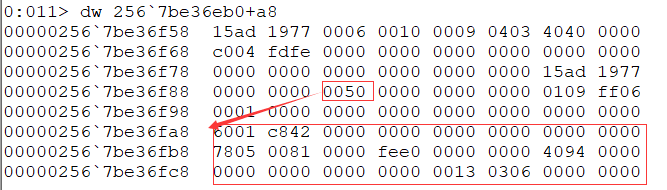
似乎capability pointer指向的偏移处都是PCI power management功能的. XHCI就是这样.
VMware workstation
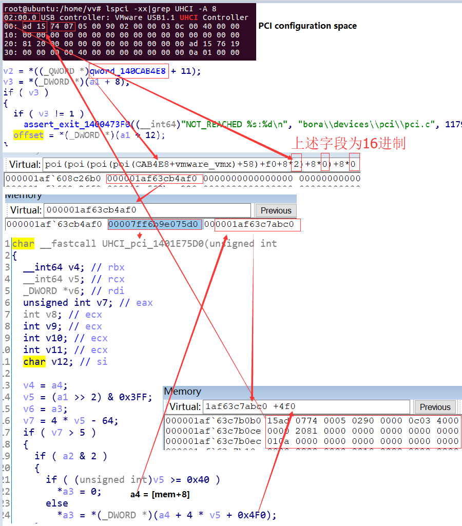
遍历PCI设备
1 | void retrieveAddress(u32 vid, u32 did, u32 *bar0, u32 *bar2) { |
Linux设备的初始化流程
1 | pci_enable_device(struct pci_dev *dev) |
名词解析
PCI Address Domain
The PCI address domain consists of three distinct address spaces: configuration, memory, and I/O space.
PCI Configuration Address Space
Configuration space is defined geographically; in other words, the location of a peripheral device is determined by its physical location within an interconnected tree of PCI bus bridges. A device is located by its bus number and device (slot) number. Each peripheral device contains a set of well-defined configuration registers in its PCI configuration space. The registers are used not only to identify devices but also to supply device configuration information to the configuration framework. For example, base address registers in the device configuration space must be mapped before a device can respond to data access.
The method for generating configuration cycles is host dependent. In IA machines, special I/O ports are used. On other platforms, the PCI configuration space can be memory-mapped to certain address locations corresponding to the PCI host bridge in the host address domain. When a device configuration register is accessed by the processor, the request is routed to the PCI host bridge. The bridge then translates the access into proper configuration cycles on the bus.
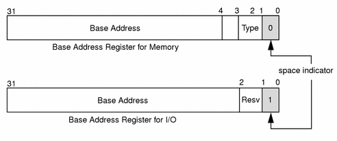
PCI Configuration Base Address Registers
The PCI configuration space consists of up to six 32-bit base address registers for each device. These registers provide both size and data type information. System firmware assigns base addresses in the PCI address domain to these registers.
Each addressable region can be either memory or I/O space. The value contained in bit 0 of the base address register identifies the type. A value of 0 in bit 0 indicates a memory space and a value of 1 indicates an I/O space. Figure A-4 shows two base address registers: one for memory; the other for I/O types.
Figure A-4 Base Address Registers for Memory and I/O
PCI Memory Address Space
PCI supports both 32-bit and 64-bit addresses for memory space. System firmware assigns regions of memory space in the PCI address domain to PCI peripherals. The base address of a region is stored in the base address register of the device’s PCI configuration space. The size of each region must be a power of two, and the assigned base address must be aligned on a boundary equal to the size of the region. Device addresses in memory space are memory-mapped into the host address domain so that data access to any device can be performed by the processor’s native load or store instructions.
PCI I/O Address Space
PCI supports 32-bit I/O space. I/O space can be accessed differently on different platforms. Processors with special I/O instructions, like the Intel processor family, access the I/O space with in and out instructions. Machines without special I/O instructions will map to the address locations corresponding to the PCI host bridge in the host address domain. When the processor accesses the memory-mapped addresses, an I/O request will be sent to the PCI host bridge. It then translates the addresses into I/O cycles and puts them on the PCI bus. Memory-mapped I/O is performed by the native load/store instructions of the processor.
PCI Hardware Configuration Files
Hardware configuration files should be unnecessary for PCI local bus devices. However, on some occasions drivers for PCI devices need to use hardware configuration files to augment the driver private information. See driver.conf(4) and pci(4) for further details.
额外信息
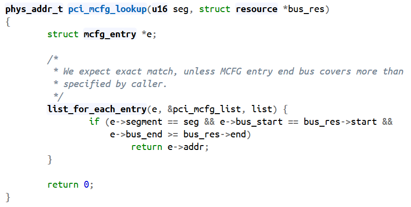
pci_mcfg_lookup
Get bus number in windows
1 | // Get the BusNumber |
ACPI
ACPI(Advanced Configuration and Power Interface)Table是BIOS提供给OSPM的硬件配置数据,包括系统硬件的电源管理和配置管理,ACPI Table有很多表,根据存储的位置,可以分为:
1) RSDP位于F段,用于OSPM搜索ACPI Table,RSDP可以定位其他所有ACPI Table
2) FACS位于ACPI NVS内存,用于系统进行S3保存的恢复指针,内存为NV Store
3) 剩下所有ACPI Table都位于ACPI Reclaim内存,进入OS后,内存可以释放
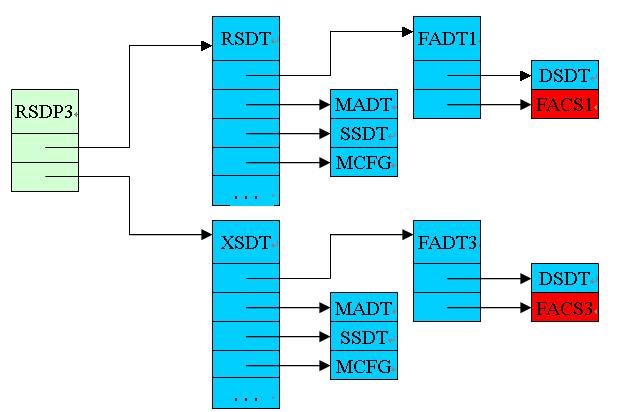
其中绿色代表在内存F段,蓝色是ACPI Reclaim内存,红色是NV store内存.
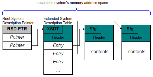
整个ACPI表以RSDP(Root System Descriptor Pointer
Table)为入口点,每个非叶子节点都会包含指向其他子表的指针,各个表都会有一个表头,在该表头中包含了相应的Signature,用于标识该表,有点类似与该表的ID,除此之外,在表头中还会包含Checksum、Revision、OEM ID等信息。所以查找ACPI表的关键就是在内存中定位到RSDP表。
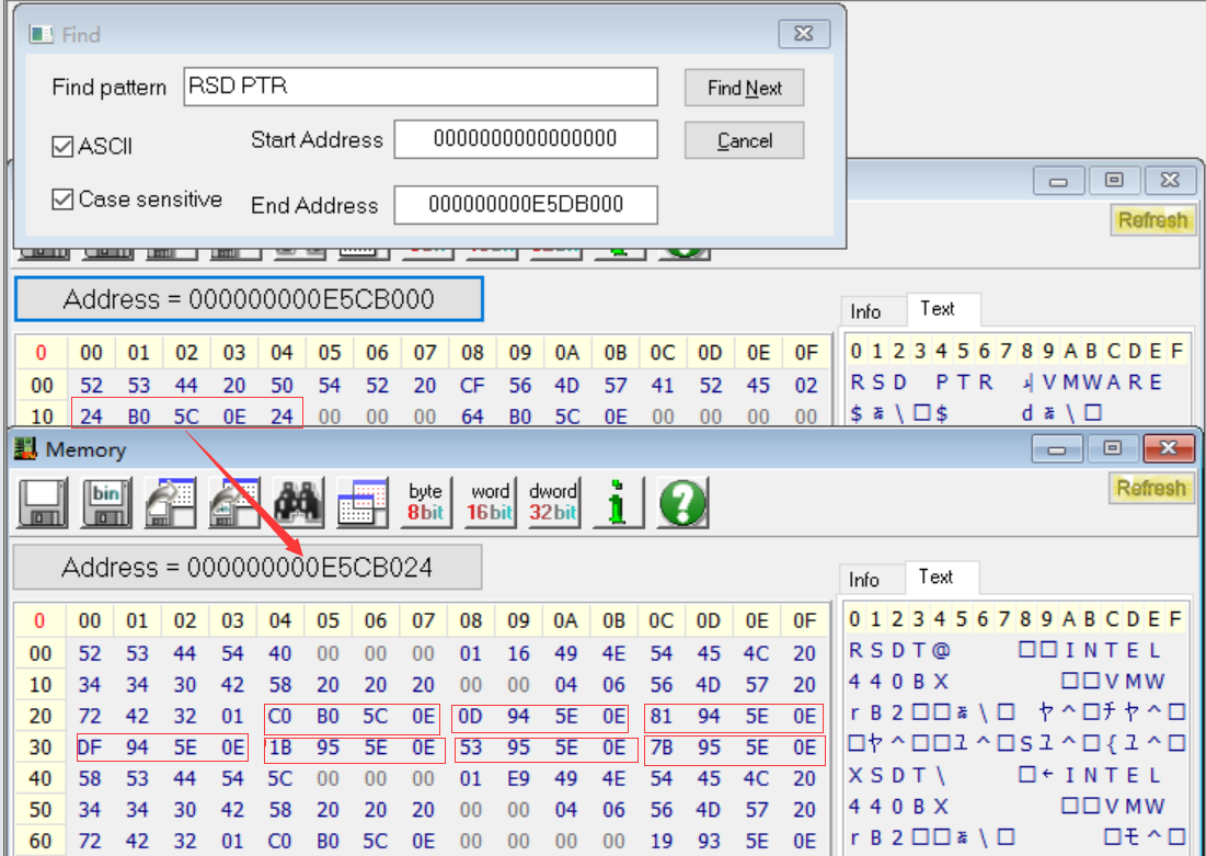
对于基于Legacy BIOS的系统而言,RSDP表所在的物理地址并不固定,要么位于EBDA(Extended BIOS Data Area, 位于物理地址0x40E)的前1KB范围内;要么位于0x000E0000 到0x000FFFFF的物理地址范围内。Linux kernel在启动的时候,会去这两个物理地址范围,通过遍历物理地址空间的方法寻找RSDP表,即通过寻找RSDP表的Signature(RSD PTR)来定位RSDP的位置,并通过该表的length和checksum来确保找到的表是正确的。
示例
The RSDT is the main System Description Table. However there are many kinds of SDT. All the SDT may be split into two parts. One (the header) which is common to all the SDT an another (data) which is different for each table.
The header structure of the header is:
1 | struct ACPISDTHeader { |
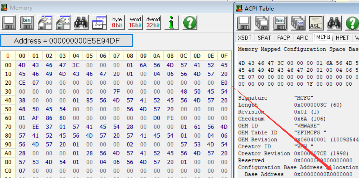
通过暴力搜索内存中的”RSD PTR”字符串, 找到对应的内容. 定位+0x10指向的地址, 得到RSDT表.参考视频
MCFG table:
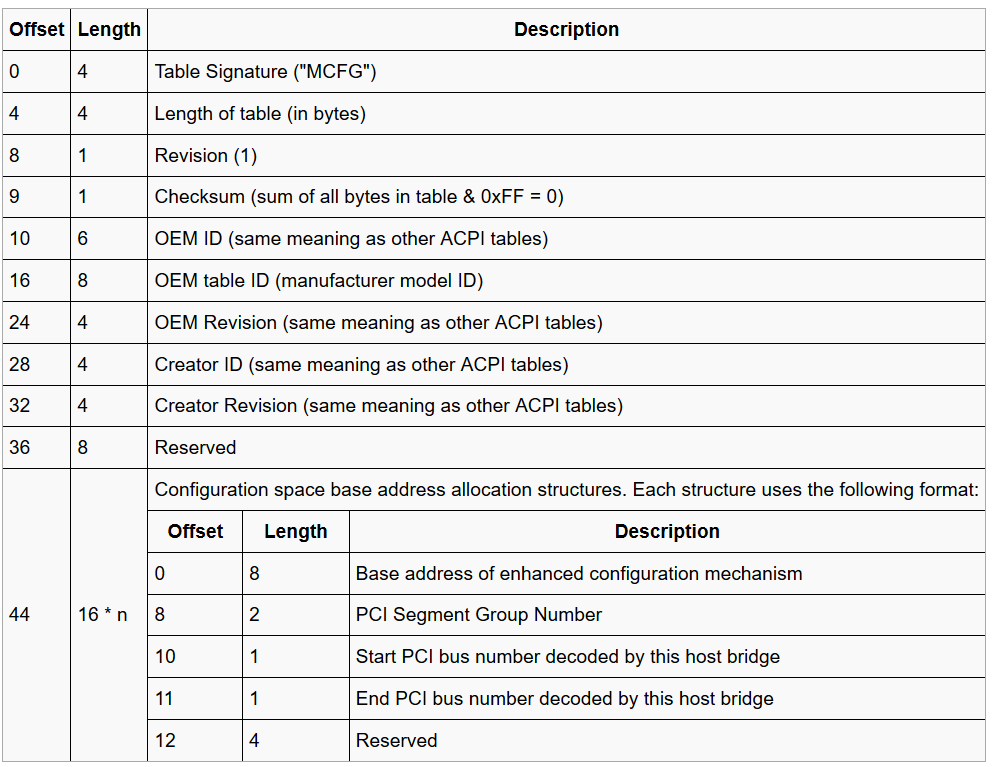
其中44(0x2C)位置的 Base Address of enhanced configuration mechanism 就是 segment(有的成为group) 为 0 的MMConfig 的地址.
Get MMCFG or MCFG in kernel
How to access pci express configuration space via MMIO? , pci express configuration space access .
windows 用户态
1 | UINT WINAPI EnumSystemFirmwareTables( |
windows 内核态
1 |
|
ATU(Address Translation Unit)
TLP中的地址哪里来?ATU转换过来的。这个问题就是这么的简单。ATU是什么?是一个地址转换单元,负责将一段存储器域的地址转换到PCIe总线域地址,除了地址转换外,还能提供访问类型等信息,这些信息都是ATU根据总线上的信号自己做的,数据都打包到TLP中,不用软件参与。软件需要做的是配置ATU,所以如果ATU配置完成,并且能正常工作,那么CPU访问PCIe空间就和访问本地存储器空间方法是一样的,只要读写即可。
这就解释了存储器地址和TLP地址字段的关系了。至此,地址相关的问题就解决了。
ATU配置举例:以kernel 4.4中designware PCIe host驱动为例
1 | static void dw_pcie_prog_outbound_atu(struct pcie_port *pp, int index, |